Safety Document Group 3
Occupational Safety Training Document for Stone Material Manufacturing

Apr
DOWNLOAD OCCUPATIONAL SAFETY DOCUMENT PACKAGE (6 GROUPS, OVER 300 INDUSTRIES)
The training material of the Occupational Safety Training Course in stone material production helps workers gain safety knowledge and prevent hazards during stone construction material manufacturing.
1. Stone Crushing Line in the Stone Material Production Safety Document
There are two main types.
The type used for crushing hard stones with a hardness index above 1000 uses a cone crusher. This type is mandatory in mountainous areas where the stone hardness intensity is high, typically from Ha Tinh province onward.
The type used for stones with hardness below 1000 uses a hammer crusher. This type is often used for limestone areas in northern mountains. However, in northern regions where the stone hardness is higher, cone crushers are still required.
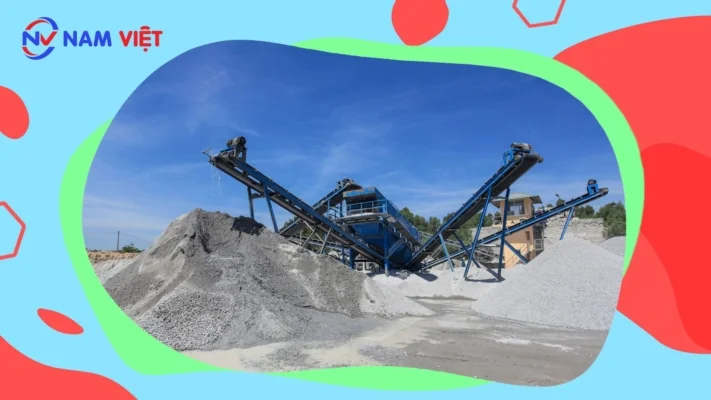
The stone crushing production line consists of a vibrating feeder, jaw crusher, impact crusher, vibrating screen, rubber conveyor belt, centralized electric control, etc., designed for an output of 50–500 tons per hour. To meet customer-specific processing requirements, cone crushers and dust extraction systems can be configured. It is commonly used for sand making and core material processing such as limestone, granite, basalt, and river gravel, suitable for industries such as hydropower, construction materials, highways, and urban construction. The combination of equipment can be adjusted based on different process requirements to satisfy each customer’s production needs.
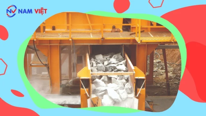
2. Basic Process of the Stone Material Production Line
Large stone blocks are fed from the vibrating feeder into the jaw crusher for primary crushing at a uniform rate. The crushed material is then transported via a rubber conveyor belt to the impact crusher for secondary crushing. After fine crushing, it moves through the conveyor to the vibrating screen for classification into different sizes to meet specific grain size requirements. Finished materials are conveyed to the final product pile, while materials not meeting the required size are returned to the impact crusher for re-crushing, forming a closed-loop cycle. The final particle size can be customized according to customer requirements. To protect the environment, dust extraction systems can be integrated.
3. Features of the Stone Material Production Line
The stone material production line is highly automated. Apart from routine maintenance during start-up and shutdown, it requires minimal manual operation. It delivers high production efficiency, low operating cost, large output, high profitability, uniform particle size, and good grain shape, meeting the material requirements for national highway standards.
The layout and installation of equipment for the stone material production line depend mainly on material size, output capacity, and application requirements of the customer. The production process is designed based on the site conditions to ensure efficiency and cost-effectiveness.
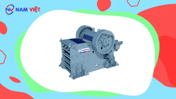
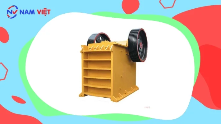
a. Jaw Crusher in the Stone Material Production Safety Document
The jaw crusher is a highly efficient and energy-saving crushing device. The range of models is comprehensive, capable of crushing materials from 125 mm to 750 mm. It is the primary equipment used in the mining industry for coarse crushing. Jaw crushers are commonly applied in mining, metallurgy, construction materials, road, railway, hydraulic, and chemical industries.
Working principle of the jaw crusher:
- The main structure of the jaw crusher includes the frame, eccentric shaft, large pulley, flywheel, movable jaw, side guard plate, liner plate, wedge adjustment device, bolts, return springs, fixed jaw plate, and movable jaw plate. The liner plate also functions as a safety component. The crushing method of the jaw crusher is a curved extrusion type. The motor drives the belt and pulley, causing the eccentric shaft to move the movable jaw up and down. When the movable jaw rises, the angle between the liner and movable jaw increases, bringing the movable jaw close to the fixed jaw, crushing the material through compression, twisting, and grinding. When the movable jaw descends, the angle decreases, and the spring and rod mechanism cause the movable jaw to move away from the fixed jaw, allowing the crushed material to be discharged. With continuous motion, the crushing and discharge processes repeat cyclically, achieving mass production.
Performance features of the jaw crusher:
- Deep crushing chamber without dead zones, improving feed capacity and output;
- High crushing ratio and uniform particle size;
- Adjustable discharge opening using shims—reliable, convenient, and flexible;
- Safe and reliable lubrication system, easy part replacement, minimal maintenance workload;
- Simple structure, reliable operation, and low operational cost;
- Energy-saving design—15% to 30% energy savings per machine, and over 1x savings for the system;
- Wide adjustment range for discharge openings to meet diverse customer requirements;
- Low noise and minimal dust emission.
Technical specifications and performance table of the jaw crusher:
| Model | Feed Opening Size (mm) | Maximum Feed Size (mm) | Processing Capacity (t/h) | Motor Power (kW) | Overall Dimensions (mm) | Weight (T) |
| PE150×250 | 150×250 | 125 | 1-3 | 5.5 | 896×745×935 | 0.8 |
| PE250×400 | 250×400 | 200 | 5-20 | 15 | 1430×1310×1340 | 2.8 |
| PE400×600 | 400×600 | 350 | 15-60 | 30 | 1700×1732×1653 | 6.5 |
| PE500×750 | 500×750 | 425 | 50-100 | 55 | 2035×1921×2000 | 10.3 |
| PE600×900 | 600×900 | 480 | 60-130 | 75 | 2290×2206×2370 | 15.5 |
| PE750×1060 | 750×1060 | 630 | 80-180 | 90 | 2655×2302×3110 | 28 |
| PE900×1200 | 900×1200 | 750 | 140-260 | 110 | 3789×2826×3025 | 52 |
| PEX250×750 | 250×750 | 210 | 10-40 | 22 | 1667×1545×1020 | 5 |
| PEX250×1000 | 250×1000 | 210 | 15-50 | 30 | 1550×1964×1380 | 6.5 |
| PEX250×1200 | 250×1200 | 210 | 20-60 | 37 | 2192×1900×1950 | 7.7 |
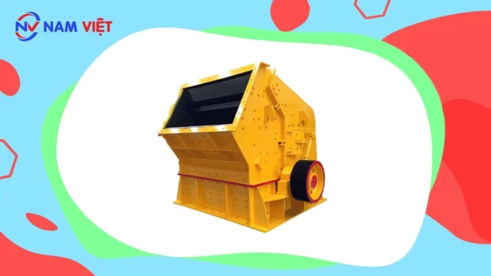
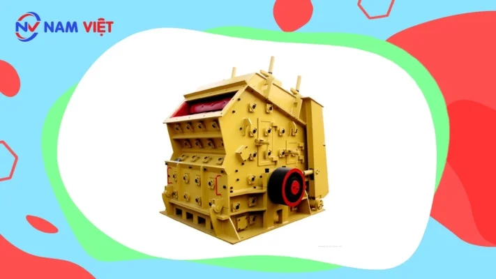
b. Impact Crusher in the Stone Material Production Safety Document
The impact crusher applies the latest manufacturing techniques and special structural design. The finished product has a cubic shape, no internal cracks, and uniform grain size. It can handle feed sizes not exceeding 500 mm, including coarse, medium, and fine materials (such as granite, limestone, concrete, etc.) with a compressive strength not exceeding 350 MPa. It is widely used in industries such as iron ore processing, railways, highways, energy, cement, chemicals, and construction. The discharge particle size can be adjusted with various specifications.
Working principle of the impact crusher:
- The impact crusher uses impact force to crush materials. When in operation, the motor drives the rotor to rotate at high speed. The material enters the impact zone and is struck by the blow bars on the rotor, then thrown onto impact plates for further crushing. The process continues as the material rebounds into the impact zone multiple times, reducing the size progressively until it reaches the required granularity and exits through the discharge opening. Adjusting the gap between the impact rack and rotor achieves different output sizes and shapes.
Performance features of the impact crusher:
- Large feed opening and high crushing chamber, suitable for high hardness and large-sized materials;
- Convenient adjustment of the impact plate gap and blow bar, enabling good particle shape control;
- Compact structure, strong mechanical rigidity, and large rotational inertia of the rotor;
- Uses chromium hammer with high impact and wear resistance;
- Pinless connection, easy inspection and maintenance, reliable and economical;
- Comprehensive crushing function, high efficiency, minimal wear parts, and high overall benefits.
Technical specifications of the impact crusher:
| Model | Specification | Feed Opening (mm) | Maximum Feed Length (mm) | Processing Capacity (t/h) | Motor Power (kW) | Weight (T) |
| PF1010 | Φ1000×1050 | 400×1080 | 350 | 50-80 | 75 | 12 |
| PF1210 | Φ1250×1050 | 400×1080 | 350 | 70-130 | 110 | 14 |
| PF1214 | Φ1250×1400 | 400×1430 | 350 | 90-180 | 132 | 18 |
| PF1315 | Φ1320×1500 | 860×1520 | 500 | 120-250 | 200 | 19 |
| PF1320 | Φ1320×2000 | 860×2030 | 500 | 160-350 | 260 | 24 |
c. Cone Crusher in the Stone Material Production Safety Document
The cone crusher is widely used in industries such as metallurgy, construction materials, road building, chemicals, and others. It is suitable for crushing medium and above-medium hardness ores and rocks. The cone crusher features strong crushing capability, high efficiency, large throughput, low operating cost, convenient adjustment, and long service life. It provides uniform particle size, reduces circulation load, and is equipped with a hydraulic cleaning system that shortens downtime. The grease sealing system prevents issues related to water and oil leakage. The spring safety system acts as overload protection, allowing uncrushable materials (such as metal plates) to pass through without damaging the machine. Cone crushers are available in standard and short-head types—the standard type for medium and coarse crushing, and the short-head type for fine and secondary crushing.
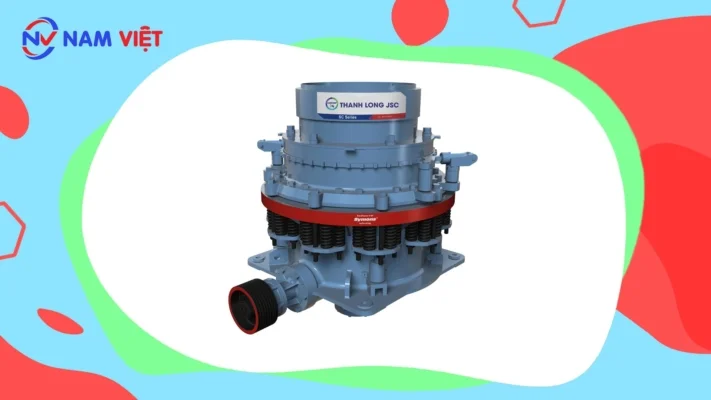
Working principle of the cone crusher:
- The working parts of a cone crusher include two conical surfaces—a fixed cone (outer cone) and a moving cone (inner cone). The fixed cone is part of the machine frame, while the moving cone is installed on an eccentric sleeve. Their axes intersect, creating an oblique angle. As the moving cone rotates around the fixed cone, it compresses, impacts, and bends the material in the crushing chamber. Crushed material discharges through the bottom opening by gravity. Feed material enters from the top feed opening.
Technical specifications of the cone crusher:
| Model | Maximum Feed Opening (mm) | Discharge Opening Adjustment Range (mm) | Processing Capacity (t/h) | Power (kW) | Weight (T) | Overall Dimensions (mm) | |
| YB | 00 | 65 | 12-25 | 12-25 | 30 | 5.5 | 2800х1300х1700 |
| YD | 35 | 3-15 | 5-23 | 5.5 | |||
| YB | 00 | 115 | 15-30 | 50-90 | 55 | 10.2 | 3050х1640х2350 |
| YZ | 60 | 5-20 | 20-65 | 10.2 | |||
| YD | 40 | 3-13 | 15-50 | 10.3 | |||
| YB | 200 | 145 | 20-50 | 110-200 | 110 | 24.7 | 4000х1900х2980 |
| YZ | 100 | 8-26 | 50-150 | 25 | |||
| YD | 50 | 3-15 | 18-105 | 25.6 | |||
| YB | 750 | 215 | 25-60 | 280-480 | 160 | 50.3 | 4870х3800х4192 |
| YZ | 185 | 10-30 | 115-320 | 50.3 | |||
| YD | 85 | 5-15 | 75-230 | 50.4 | |||
| YB | 200 | 300 | 30-60 | 59-1000 | 260-280 | 80 | 5420х4300х4870 |
| YZ | 230 | 10-30 | 200-580 | 80 | |||
| YD | 100 | 7-16 | 120-340 | 81.4 | |||
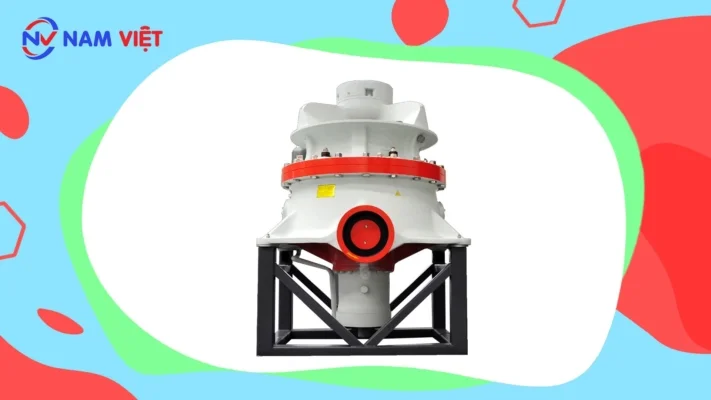
d. Hydraulic Cone Crusher High Performance Series in the Stone Material Production Safety Document
The new High Performance hydraulic cone crusher series not only increases crushing capacity and efficiency but also broadens the application range, from limestone to basalt, and from stone material production to crushing various iron ores. It can perform medium crushing, fine crushing and ultra fine crushing. As a modern generation product that replaces spring cone crushers and conventional hydraulic cone crushers in mining and construction, it is the most suitable equipment for large scale stone material plants and ore crushing operations.
Technical features and advantages of the hydraulic cone crusher:
- The High Performance hydraulic cone crusher is superior to spring cone crushers and conventional hydraulic cone crushers.
- It uses high rotational speed combined with an optimized stroke to raise the rated capacity and throughput of the crusher, improving crushing ratio and productivity.
- The design is rational with advanced crushing principles and specifications. Operation is reliable and operating cost is low. Wear parts are protected to minimize repair costs. Service life can be extended by thirty percent or more.
- By optimizing the crushing chamber and rotational speed, the crusher adopts a stratified crushing principle instead of traditional comminution. This selective crushing increases the proportion of desired sized product and reduces the production of flaky particles.
- Hydraulic protection and hydraulic chamber clearing raise the automation level and reduce downtime.
- The hydraulically adjustable discharge opening and overload protection improve operability, simplify maintenance, shorten shutdown time; the hydraulic cylinder allows steel plates and other tramp metal to pass through the chamber. When tramp metal passes or becomes lodged, the top section automatically opens to discharge it, which reduces manual unblocking that caused shutdowns in older crushers. Lubrication is advanced and reliable, extending service life.
- A specially designed sparse lubrication system further extends equipment life. A non contact high performance sealing system reduces wear and improves dust sealing reliability, fundamentally resolving the oil water mixing problems common to older spring cone crushers.
- The HP cone crusher only requires replacement of the fixed and movable cone liners; the crushing chamber can be adjusted from the standard super coarse chamber to the short head ultra fine chamber as required, meeting a wide range of product size specifications.
- All major components of the HP cone crusher can be disassembled and serviced from the top or side. Disassembly of the moving cone and fixed cone is convenient without removing the main frame or connecting bolts, so liner replacement is easier during routine maintenance. Using a hydraulic drive delivers optimal production performance.
- The machine provides higher production capacity, produces well shaped particles, features simple automatic control, high reliability and flexibility, thereby creating significant value for customers.
Technical specifications of the hydraulic cone crusher:
| Model | Chamber Type | Feed Size (millimeter) | Minimum Discharge Size (millimeter) | Capacity (tons per hour) | Power (kilowatt) | Weight (metric ton) |
| HPC-160 | C | 150 | 13 | 120-240 | 160 | 13 |
| F | 76 | 6 | 55-180 | |||
| HPC-220 | C | 225 | 13 | 150-430 | 220 | 18 |
| F | 86 | 6 | 90-260 | |||
| HPC-315 | C | 290 | 13 | 190-610 | 315 | 26 |
| F | 100 | 6 | 108-320 | |||
| HPC-400 | C | 320 | 13 | 230-700 | 400 | 33 |
| F | 100 | 8 | 145-430 |
Note: Pay attention to the process conditions such as the physical properties of the material and expected capacity, the feeding method, the feed particle size and composition, and similar factors.
The capacity table for the HP hydraulic cone crusher is provided only as a reference to indicate the normal working capacity of the crusher. The crusher is one component of the complete production line. Therefore, its performance will be affected by proper selection and operation of the feeder, conveyor belt, vibrating screen, motor, drive units and stockpile. Please pay attention to these factors in order to improve the output and performance of the hydraulic cone crusher during operation.
- Precisely select the crushing chamber type according to the specific material to be crushed;
- Ensure an appropriate integrated particle size distribution;
- Maintain even feeding distribution within a full 360 degree range inside the crushing chamber;
- Use automatic control equipment;
- Keep the crusher discharge area unobstructed;
- Match conveyor specification and maximum handling capacity with the crusher capacity;
- Pre select appropriate screening capacity and closed circuit screening configuration.
Factors that reduce the output of the HP hydraulic cone crusher include:
- Fine material smaller than the discharge opening comprising more than ten percent of the feed;
- Presence of sticky or clayey material in the feed;
- Lack of feed control;
- Uneven distribution of feed pulses into the crushing chamber;
- Failure to use the recommended cone configuration;
- Insufficient screening capacity in the closed circuit system;
- Obstructions in the crusher discharge area;
- Feed material that is excessively hard or highly abrasive.
e. Circular Vibrating Screen in the Stone Material Production Safety Document
The circular vibrating screen is a new screening device for particle classification. The vibrating track is circular and it is specially designed for ore and rock classification at quarries. It is also provided for coal preparation, ore dressing, construction materials, power plant and chemical industries to grade products. The circular vibrating screen features an advanced structure, strong anti vibration capacity, low noise, easy maintenance and long service life. With an eccentric shaft vibration exciter and adjustable eccentric baffles to control amplitude, and an advanced riveted frame structure, service life is increased and spring vibration impact is reduced. This is a new type of multi deck circular vibrating screen with high efficiency.
Working principle of the circular vibrating screen:
The motor drives the eccentric plate of the vibration exciter to generate high speed circular motion. The eccentric plate produces a large centrifugal force that stimulates the screen box to produce a circular motion with a defined amplitude. Material on the screen receives impulse from the vibrating box and moves in a continuous tossing motion along the inclined screen surface. During this motion, finer particles pass through the screen apertures and grading is achieved.
Technical specifications of the circular vibrating screen:
| Model | Screen Surface Size (millimeter) | Number of Screen Decks | Screen Aperture Size (millimeter) | Maximum Feed Length (millimeter) | Processing Capacity (tons per hour) | Power (kilowatt) | Vibration Frequency (revolutions per minute) | Two Amplitude Values (millimeter) |
| 2YZS1237 | 3700×1200 | 2 | 3-100 | 400 | 10-80 | 11 | 750-950 | 5-9 |
| 3YZS1237 | 3700×1200 | 3 | 3-100 | 400 | 10-80 | 11 | 750-950 | 5-9 |
| 2YZS1548 | 4800×1500 | 2 | 3-100 | 400 | 30-200 | 15 | 750-950 | 5-9 |
| 3YZS1548 | 4800×1500 | 3 | 3-100 | 400 | 30-200 | 15 | 750-950 | 5-9 |
| 2YZS1848 | 4800×1800 | 2 | 3-100 | 400 | 50-250 | 18.5 | 750-950 | 5-9 |
| 3YZS1848 | 4800×1800 | 3 | 3-100 | 400 | 50-250 | 18.5 | 750-950 | 5-9 |
| 4YZS1848 | 4800×1800 | 4 | 3-100 | 400 | 50-250 | 18.5 | 750-950 | 5-9 |
| 2YZS1860 | 6000×1800 | 2 | 3-100 | 400 | 65-586 | 22 | 750-950 | 5-9 |
| 3YZS1860 | 6000×1800 | 3 | 3-100 | 400 | 65-586 | 22 | 750-950 | 5-9 |
| 4YZS1860 | 6000×1800 | 4 | 3-100 | 400 | 65-586 | 22 | 750-950 | 5-9 |
| 2YZS2160 | 6000×2100 | 2 | 3-100 | 400 | 81-720 | 30 | 700-900 | 5-9 |
| 3YZS2160 | 6000×2100 | 3 | 3-100 | 400 | 81-720 | 30 | 700-900 | 5-9 |
| 4YZS2160 | 6000×2100 | 4 | 3-100 | 400 | 81-720 | 30 | 700-900 | 5-9 |
| 2YZS2460 | 6000×2400 | 2 | 3-150 | 400 | 100-500 | 30 | 700-900 | 5-9 |
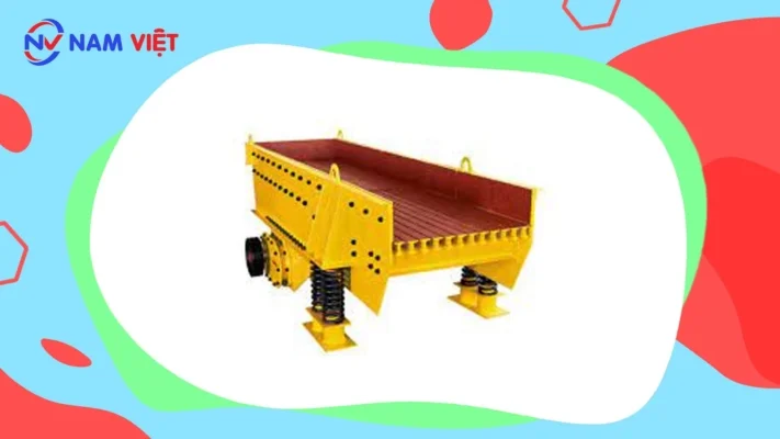
f. Vibrating Feeder in the Occupational Safety Document for Stone Material Production
The vibrating feeder, also known as the vibrating feeding machine, is designed and manufactured by our company under the GZD series. It is a new type of feeder specifically designed for transporting large-sized materials before they enter the medium and coarse crushing stages in crushing and screening processes. The vibrating feeder adopts a special dual eccentric shaft vibration mechanism, which ensures that the equipment can withstand the impact of large materials falling onto it, while providing high feeding capacity.
During production, it can continuously and evenly transport block and granular materials from the storage hopper to the receiving device, preventing the receiving equipment from being overloaded or stopped due to uneven feeding, thereby prolonging its service life. The feeder structure is divided into two types: steel plate structure and grid section structure. The steel plate feeder is generally used in stone production lines to evenly feed all materials into the crusher; while the grid section feeder can screen and classify coarse materials, making the system more economical and rational. This makes it an indispensable piece of equipment in the crushing and screening process. Therefore, it is widely used in metallurgy, mining, ore beneficiation, building materials, chemical, and abrasive material industries.
Working Principle of the Vibrating Feeder:
The GZD series vibrating feeder consists of the feeding trough, vibration exciter, spring support, and transmission device. The vibration exciter, which drives the feeding trough to vibrate, comprises two eccentric shafts (main and auxiliary) and meshed gears. The motor drives the main shaft through a triangular belt, and the gears on the main and auxiliary shafts rotate in opposite directions simultaneously, causing the trough to vibrate. This vibration continuously moves the materials forward, achieving the purpose of material feeding.
Features of the Vibrating Feeder:
This type of vibrating feeder provides stable vibration, reliable operation, low noise, low energy consumption, no material surging, long service life, easy maintenance, light weight, compact size, convenient installation and adjustment, and overall good performance. When equipped with a sealed body structure, it can effectively prevent dust pollution.
Technical Specifications:
| Model | Feeding Trough Size (mm) | Maximum Feeding Size (mm) | Processing Capacity (t/h) | Motor Power (kW) | Overall Dimensions (mm) | Weight (kg) |
| GZD-960×3800 | 960×3800 | 500 | 120-210 | 11 | 3850×1950×1630 | 3980 |
| GZD-1100×4200 | 1100×4200 | 580 | 200-430 | 15 | 4400×2050×1660 | 4170 |
| GZD-1100×4900 | 1100×4900 | 580 | 280-500 | 15 | 5200×2050×1700 | 4520 |
| GZD-1300×4900 | 1300×4900 | 650 | 450-600 | 22 | 5200×2350×1750 | 5200 |
g. Rubber Conveyor Belt
The rubber conveyor belt produced by our company efficiently transports various materials. In industrial production, rubber conveyors serve as essential links between mechanical equipment, enabling continuous and automated production processes that enhance productivity and reduce labor intensity.
The movement of the conveyor is based on the principle of frictional transmission. It features a large conveying capacity, long conveying distance, stable operation, minimal noise, simple structure, easy maintenance, low energy consumption, and standardized components. Therefore, rubber conveyor belts are widely used in mining, metallurgy, chemical industries, casting, construction materials, hydropower stations, ports, and production lines for transporting bulk or packaged materials.
According to process requirements, conveyors can operate individually or in combination with multiple conveyors or other conveying systems, arranged horizontally or inclined, to meet different layout and production line requirements. The rubber conveyor belt operates in ambient temperatures ranging from −20°C to +40°C, with material temperatures below 50°C.

Components of the Rubber Conveyor Belt:
The belt conveyor consists of the machine frame, belt, belt roller, tensioning device, and transmission device. The rubber belt conveyor uses high-quality steel plates for connection. The height difference between the front and rear supports forms an inclined plane. The machine frame is equipped with rollers, idlers, and supports for the belt traction system. There are two transmission modes: motor-reducer drive and motorized drum drive.
| Rubber Belt Width (mm) | Belt Length (m) / Power (kW) | Conveying Speed (m/s) | Conveying Capacity (t/h) | ||
| 500 | ≤12/3 | 12-20/4-5.5 | 20-30/5.5-7.5 | 1.3-1.6 | 45-100 |
| 650 | ≤12/4 | 12-20/5.5 | 20-30/7.5-11 | 1.3-1.6 | 70-120 |
| 800 | ≤6/4 | 6-15/5.5 | 15-30/7.5-15 | 1.3-1.6 | 120-180 |
| 1000 | ≤10/5.5 | 10-20/7.5-11 | 20-40/11-12 | 1.3-2.0 | 160-250 |
| 1200 | ≤10/7.5 | 10-20/11 | 20-40/15-30 | 1.3-2.0 | 200-400 |